The first noisy
suppressor circuits appeared in the market around early seventies.
Among them the most used ones were sold under the trade names:
DBX and Dolby
Therefore, even considering the improvement brought by such
innovations, the recording sound analogically still presented
distortions.
Such technical situation was based in the new measuring parameters
used for the evaluation of the recording dynamic range allowed
by the three known recording media: magnetic tape, discs and
frequency modulation broadcasting mode.
Thus the dynamic range or the quantity of signal related with
the noisy level and the distortion were far behind the wanted
quality since the recorded sound still had spurious signals.
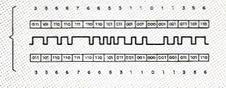
Fig 334
| THE
DOLBY SYSTEM |
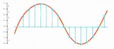
Music and noisy: music consists
of sounds of different pitch and loudness, separted by
intervals of silence shown in the diagram by decrescnt
lines.
Noisy or hiss is due to the physical-chemical of the midia;
they are recorded with the sound signals and so reducing
the music level.
|
The
Dolby B system operates in the following way:
a) Before the recording it listens to the music to find
the places where the nois might later be heard in the
playback.
|
b)
During the recording, by using an electronic method, it
increase automtically the music volume in such way it
is recorded at a higher level thant the normal.
c) During the playback, the volume
is automatically reduced in all the places where it
was increased during the recording.
|
This makes
the music sound exactly right, because the loudness of
every note is just the same as it was at the start at
the same time the noisy of the tape, which is now mixed
with the music, is reduced in all of the same places. |
 |
| Fig. 334 - The principle
of the Dolby noisy reduction system, invented by the American
electronic engineer Dr. Ray Dolby used in the majority
of domestic tape recorders. |
By a careful evaluation in each stage of the audio chain, the
engineers found that to improve the quality of the recorded
sound it was mandatory to concentrate the researching efforts
in the recording area in such way to be able to develop a new
higher dynamic range and distortion free sound recording technique.
Around 1980 the engineers started to use the “pulse code
modulation” in order the analogical signals from the original
sound source could be digitized either for recording and playback.
In the reality the pulse code modulation technique, as known
as PCM can be defined as a modulation method requiring code
to digitize a analogical wave.
Basically its principle consists that the original musical signal
is sampled at a fixed frequency, and the value of the sampled
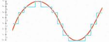
level is ascertained. Fig 335
|
Sampling |
Step where the analog signals are sampled
in thousands of parts in such away the same could be recovered
entirely again. |
|
|
Quantization |
Step where the signal sampled is then
quantized. During quantization, a continuous amplitude
analog signal is processed to produce a signal consisting
of a finite number of discrete levels of amplitude and
so it can have a slight discrepancy or the quantization
error as know as quantization noisy. The error can be
reduced in such away for every increase in number of steps
used, there is a coresponding reduction in height of each
steps. |
|
|
Coding |
Step where the quantized sample values
are converted in a binary code. |
|
|
Decoding |
A reverse step where the coding
values is converted in quantized samples, which have same
values as before the quantization. |
|
|
Low-pass filter |
It is responsible for the original signal
recovery considering only the sampling parts contained
in the original signal and so cuting off the entire undesired
frequency spectrum generated during the sampling. |
|
| Fig 335 - The diagram of the PCM
technique. |
The value of each samples level is then converted into binary
notation. Fig 336
Thus, for example, the resolution of the system used could
be either 14 or 16 bits. The configuration of bits used is
known as the quantization bits, and it is accepted that 14
or 16 bits systems are mostly common used. The PCM modulation
method is complete when digital values representing each original
sampled level are collated.
The PCM signal encoded in this way has the following major
advantages: it is immune to distortion. Even if the original
signal is subject to distortion, sampling at a fixed level
allows the reproduction of the original in as near perfect
way a way as possible.
|
BINARY
AND DECIMAL NOTATION |
| Decimal |
Binary |
| 1 |
1 |
| 2 |
10 |
| 3 |
11 |
| 4 |
100 |
| 5 |
101 |
| 6 |
110 |
| 7 |
111 |
| 8 |
1000 |
| 9 |
1001 |
| 10 |
1010 |
| 11 |
1011 |
| 12 |
1100 |
It is based on ten different numeral from
0 to 9. Numbers great than 9 are indicated by combinations
of the ten basic digits in different columns as the “undreds”,
“tens” and “units”.
For instance: 10
The combinations of use the two different numerals only
or 1 and 0. To express numbers greater than 1 it must
use other columns such as “twos”, “fours”,
“eiths” and so forth, similar to the decimal
system.
For instance: 1010 |
| Practically speaking the
binary digits indicate a permanent yes and no mode. In
the PCM system uses pulses to express the sampled values
or they can only express” on” or “off”.
By using a decimal system it cannot use ten different
numerals to express these patterns of the PCM pulses. |
| Fig. 336 - Chart comparing the decimal
and binary notation. |
Multiplexing or many different signals can be mounted in one
PCM signal without any crosstalk between the different signals.
The signal-to-noisy ratio, which defines the musical quality,
is related with the number of quantization bits used at the
time of reproduction. Thus, if a large number of quantization
bits are used, it is possible to obtain an astoundingly signal-to-noisy
ratio far beyond in the analogical method.
 |
 |
| Fig. 337 - The videodisc launched in
the market by Philips circa 1970. |
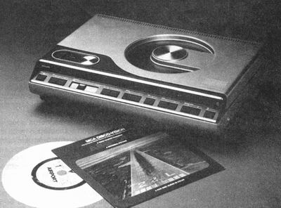
Fig. 338 - The Compact audio disc
Courtesy: Philips Brazil, 1980. |
The PCM technique for audio application started to be used
in later sixties in Japan, by using helical scans video tape
recorders. Considering the bandwidth needed to record a video
signal on videodiscs was more than the needed to record a
digitized sound signal, the same system could be used for
the former purpose.
Bearing those aspects in mind several types of equipments
were developed in order to improve the recording density,
as while in the analogical recorders require an ac bias to
achieve the necessary linearity in the PCM tape recorders
do not. Thus, engineers developed the either the rotary head
video tape recorders as well as the stationary head types,
capable of recording and dispersing one channel of data on
a plurality of tracks.
In 1980 such kind of PCM recorder was used to record high
quality “Long Playing” discs.
Therefore, soon new types of equipments and recording techniques
were developed as the DAD or Digital Audio System –
fig 337
In mid eighties the companies Sony and Philips merged their
digital techniques acquired from the former DAD method and
so they suggested the well-known and universal adopted Compact
Disc as known as CD. Fig 338
This new method to record the live sound has revolutionized
the phonographic industry. It was a direct consequence of
the merging LASER technology with the digital reproduction,
which certainly improved either the quality of the recording
as its popularization by using a practical compact and full
automatic disc player.
|